By clicking “Accept All Cookies”, you agree to the storing of cookies on your device to enhance site navigation, analyze site usage, and assist in our marketing efforts.*

All Blogs/Network
28 Aug 2026
6 min read

Switching & VLANs

Switching & VLANs

By: Martian Corporation

Introduction

“A larger network does not just need more connections — it needs better organization.”

A small office can work perfectly well with a single switch and a handful of connected devices. But as the network grows, computers, printers, phones, servers, access points, and guest devices all begin sharing the same infrastructure.

That creates a new challenge. How does a switch know where to send a frame? How can one physical network support different groups without putting everyone into the same broadcast domain? And how can multiple switches work together without creating loops?

This is where switching, VLANs, trunking, and Spanning Tree Protocol (STP) become essential.

1. A Switch Learns Where Devices Live

“A switch does not need to know the whole network — it only needs to know where the next device is.”

When an Ethernet frame arrives at a switch, the switch first looks at its source MAC address. It records that address along with the port where the frame arrived.

For example, if a computer connected to Port 3 sends a frame, the switch can learn: Computer A MAC → Port 3. Over time, these entries form a MAC address table.

When another frame arrives, the switch checks its destination MAC address against this table. If it already knows where that device is connected, it forwards the frame only toward the appropriate port.

If the destination is unknown, the switch floods the frame through the relevant ports. Once the destination responds, the switch can learn its location and handle future frames more efficiently.

This is one of the fundamental differences between a switch and an old-style hub. A hub simply repeats traffic, while a switch makes forwarding decisions based on MAC addresses.

The result is a network where traffic can be directed rather than unnecessarily repeated.
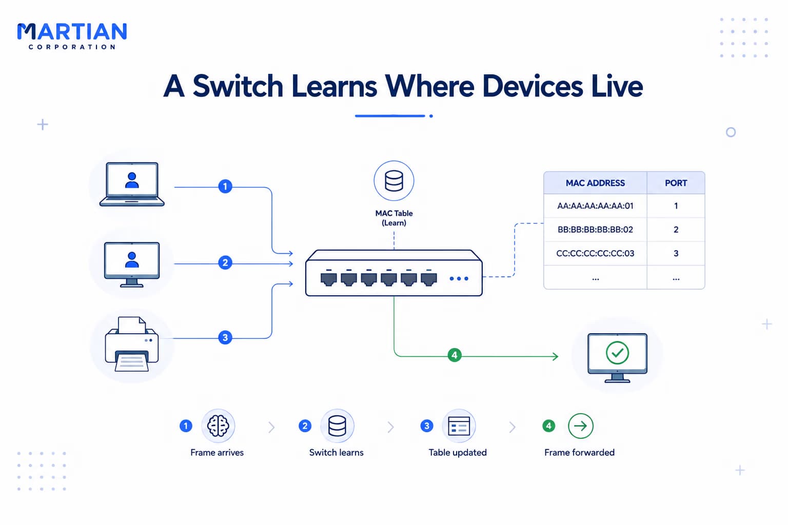
A Switch Learns Where Devices Live

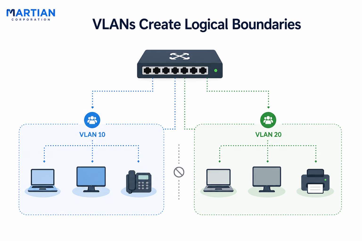
2. VLANs Create Logical Boundaries

“One physical network does not have to be one logical network.”

As an office grows, keeping every device in the same Layer 2 network creates a large broadcast domain. Broadcast traffic can reach many devices that do not actually need to receive it.

A Virtual Local Area Network (VLAN) provides a way to divide one physical switching infrastructure into multiple logical networks.

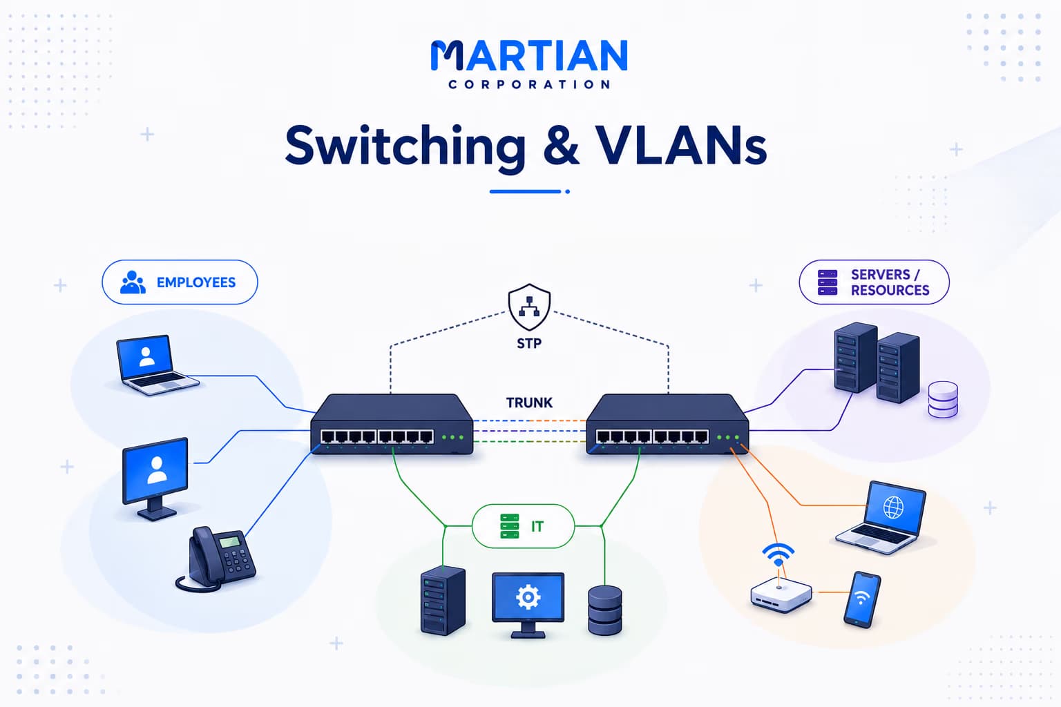
Imagine an office with three groups: VLAN 10 → Employees, VLAN 20 → IT, VLAN 30 → Guests. The devices can still use the same physical switches and cables, but the VLANs keep their Layer 2 traffic logically separated.

Devices within the same VLAN belong to the same broadcast domain. Devices in different VLANs are separated at Layer 2 and generally require a Layer 3 device to communicate with each other.

This is useful for more than organization. VLANs can reduce unnecessary broadcast traffic, create clearer security boundaries, and make network management easier. For example, guest devices can be placed into their own VLAN instead of sharing the same local network as internal company systems.

The physical infrastructure stays shared. The logical network becomes separated.

VLANs Create Logical Boundaries

3. Trunks Carry VLANs Between Switches

“Logical separation is useful only when that separation can travel across the physical network.”

Now imagine the office has two switches. Some Employee devices are connected to Switch A, while other Employee devices are connected to Switch B. Both groups still need to belong to VLAN 10.

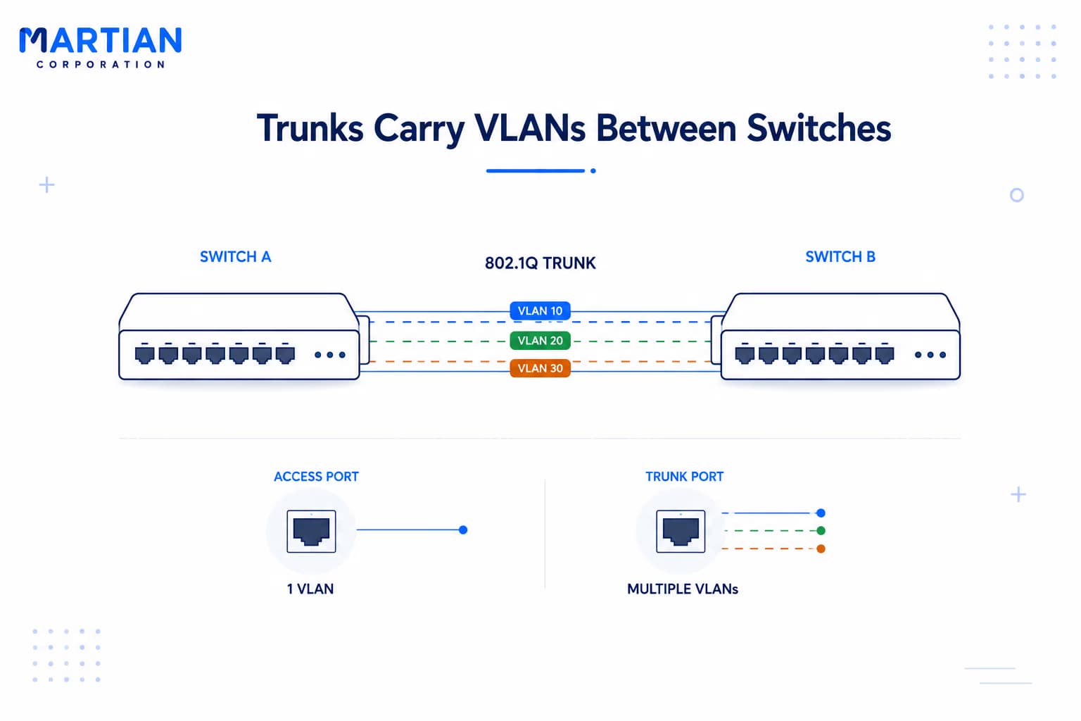
The link between the switches therefore needs to carry traffic for multiple VLANs. This is where trunking comes in.

A trunk link can carry traffic belonging to several VLANs across one physical connection. Ethernet commonly uses IEEE 802.1Q tagging to identify which VLAN a frame belongs to as it travels across the trunk.

Conceptually: Switch A → Trunk → Switch B, carrying VLAN 10 + VLAN 20 + VLAN 30.

An end-device connection is commonly an access port, associated with a particular VLAN. A trunk, on the other hand, is designed to transport multiple VLANs between network devices.

This is what makes VLANs practical in larger networks. Instead of building separate physical networks for every department, an organization can use shared switching infrastructure while keeping the traffic logically separated.

Trunks Carry VLANs Between Switches

4. STP Keeps Redundant Networks From Looping

“Redundancy protects a network — until redundancy creates a loop.”

Network engineers often add multiple links between switches so that another path is available if one connection fails. But Ethernet has a problem with physical loops.

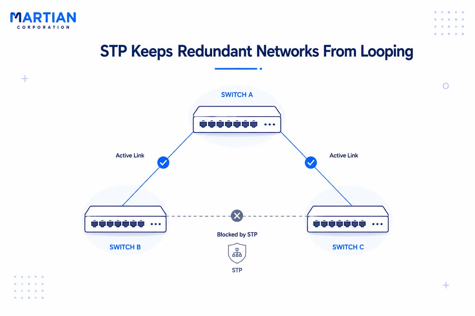
Imagine three switches connected in a triangle. A broadcast frame could travel around the loop repeatedly. Broadcast traffic can multiply, MAC address learning can become unstable, and the network can quickly become overwhelmed.

This is where Spanning Tree Protocol (STP) helps.

STP allows switches to identify redundant paths and logically place some links into a blocking state. The physical connection remains available, but it is not actively forwarding traffic while another path is being used.

If the active path fails, the network can use the redundant path. Think of it like two roads connecting the same two cities. Keeping both roads available is useful, but traffic should not be allowed to circulate endlessly between them.

Modern networks commonly use improved versions of the original STP approach, but the basic principle remains: redundancy without Layer 2 loops.

STP Keeps Redundant Networks From Looping

A Simple Office Calculation

“Good network design is also about understanding what the numbers mean.”

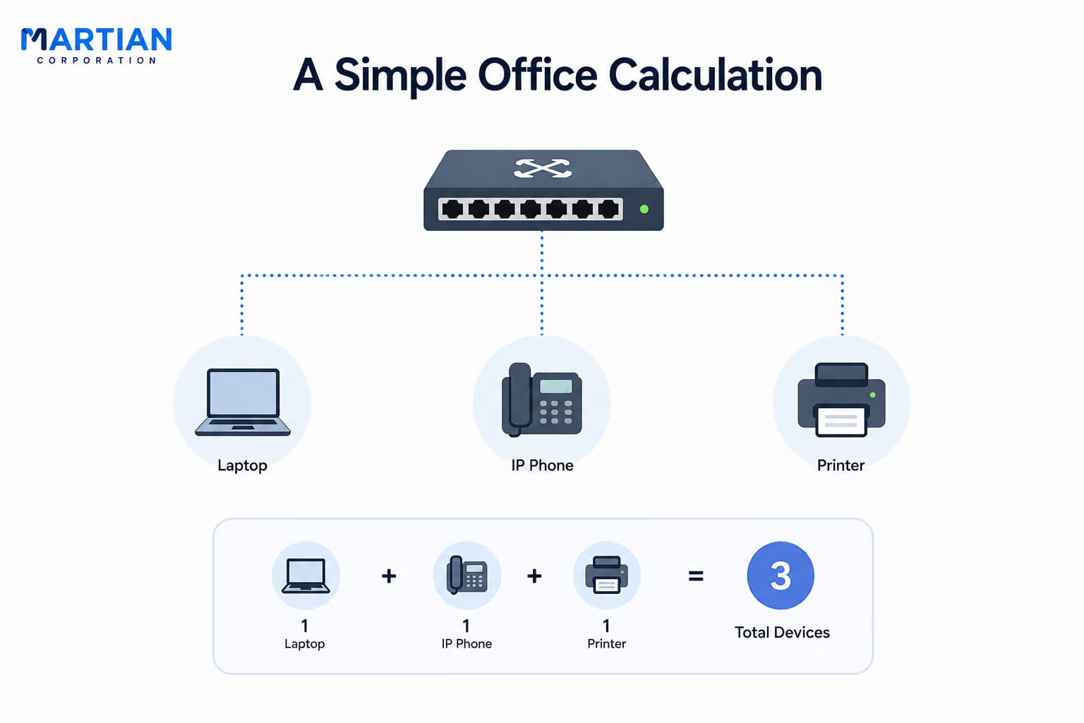
Imagine an office has 60 devices and all of them are placed into one VLAN.

That creates: 60 devices → 1 broadcast domain.

Now divide the office into three VLANs: Employees → 30 devices, IT → 10 devices, Guests → 20 devices.

The physical network has not changed — there are still 60 devices. But logically, it now has 3 VLANs → 3 broadcast domains.

So instead of every broadcast potentially reaching all 60 devices, a broadcast from the Employee VLAN remains within that VLAN unless routing or another mechanism deliberately carries the traffic elsewhere.

The point is not that VLANs magically eliminate traffic. They provide control over where Layer 2 traffic belongs. That becomes increasingly valuable as the network grows.

A Simple Office Calculation

Conclusion

“Switching connects devices; VLANs give those connections structure.”

A switch learns MAC addresses and uses its MAC table to forward frames efficiently. VLANs divide a physical switching infrastructure into logical networks, creating clearer broadcast domains and useful segmentation.

Trunking allows multiple VLANs to travel between switches over shared links using mechanisms such as 802.1Q, while STP prevents redundant Layer 2 connections from creating loops.

Put these ideas together in an office and the purpose becomes clear. Employees, IT systems, guest devices, phones, and servers can share the same physical infrastructure without necessarily sharing the same logical network.

That is the real value of switching and VLANs: not simply connecting more devices, but creating a network that can grow without becoming chaotic.

And once different VLANs exist, the next question naturally follows: how do devices in different VLANs communicate with each other?

NewsLetter

Stay ahead in the world of technology

Get curated technology trends, expert analysis, and product updates delivered straight to your inbox — no noise, just signal.

Enter your email address

By subscribing you agree to our Terms and Conditions and Privacy Policy

More Blogs

Data Link Layer, MAC Addresses & EthernetNetwork
26 Aug 2026
5 min read

Data Link Layer, MAC Addresses & Ethernet

Before data can travel across the Internet, devices must first communicate reliably within their local networks. The Data Link Layer plays a crucial role in this process by managing device-to-device communication through MAC addresses, Ethernet frames, switches, and error detection mechanisms. This article explores how the Data Link Layer works, how MAC addresses identify devices, and how Ethernet and network switches move frames across a local network—providing the foundation for efficient and reliable network communication.

Read more
The Physical Layer: Cables, Signals & MediaNetwork
21 Aug 2026
5 min read

The Physical Layer: Cables, Signals & Media

The Physical Layer: Cables, Signals & Media Every network begins with something physical — electrical signals through copper, pulses of light through fiber, or radio waves through the air. In this article, we take a closer look at the Physical Layer of the OSI Model and understand how data actually travels between devices. We’ll explore copper cables, twisted-pair wiring, fiber optic communication, wireless networks, bandwidth, throughput, latency, signal encoding, connectors, and networking standards — the building blocks that make modern computer networks possible. Because before packets can be routed, addressed, or delivered, they first need a physical medium to travel through.

Read more
How Data Actually Travels: A Packet's JourneyNetwork
19 Aug 2026
5 min read

How Data Actually Travels: A Packet's Journey

Every time we send a message, open a website, stream a video, or download a file, enormous amounts of data travel across complex networks in the form of tiny packets. But how does this data actually reach its destination? This article explores the journey of a data packet—from being broken down at the source to being addressed, routed, transmitted, and reassembled at its destination. Understanding this process provides a clearer picture of how the Internet moves information across interconnected networks, often in just milliseconds.

Read more